Problem statement:
Given the desired fixtured configurations of several parts, determine fixture contact points that can hold the parts stably, be loaded without jamming, and can minimize the positioning errors of key points due to thermal effects and machining errors.
Initial fixture design studies have considered subsets of the stated goals.
Stability and Thermal Compliance
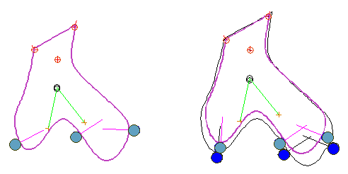
The part (purple curve and interior) in the figure below is to be held by three thermally compliant fixels (solid light blue circles) to balance a range of possible external loads (any force downward through black double circle and inside the green cone) and to minimize the thermally induced motions of the three key points (red circles with inscribed plus signs). In the picture on the left, the fixels are shown in locations chosen by a designer.
The picture on the right shows the optimal locations of the fixels (found in about 10 sec. in Matlab). The light blue fixels indicate their "cold" positions and the dark blue the "hot" postions (exagerated). Similarly, the part's "cold" and "hot" shapes are shown in purple and black. Since the part was assumed to be solid, the relative thermal motions of the key points could not be prevented, but the result shows that their gross motion was removed. This is evidenced by the fact that the hot and cold boundaries of the part nearly coincide near the key points.

|
Stability and Stack-Up
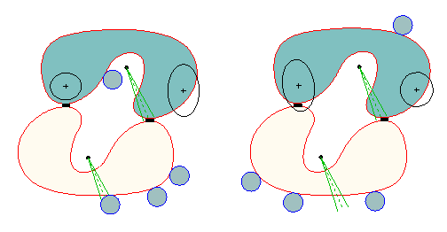
In this example, two parts in contact with spacers (black bars) are to be fixtured so as to minimize the variability of the locations of two key points on the top part (black "plus" signs) and to maintain stability in the face of uncertain loading represented by the green force cones. The tolerance on the part geometries are given as maximal excursions of the boundary points in their normal directions. The position of the center of the fixels and their geometries are assumed to be twenty times more accurate than the parts, and the spacers are assumed to be perfectly accurate. In the figure below, worst-case excursions of the key points are represented by ellipses centered at the key points. The picture on the left (right) shows the fixture design that minimizes the excursions of the key point on the left (right) while maintaining stability of the parts even if friction is absent.

|
Jam-Free Loading
When a part is placed in a fixture, it must achieve all the intended contacts in order to accurately position and orient the part. When contacts cannot be directly observed, fiducials and gauges are sometimes used to infer whether or not contacts have been achieved.
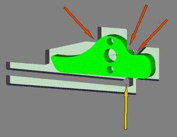
An alternative is to design fixture and part geometries such that after initial placement of the part into the fixture, one can push on the part in a particular region to guarantee (under rigid body dynamics with Coulomb friction) proper seating. The pawl (green) in the fixture (gray) below must make contact at the three points indicated by the orange arrows. The stiffness and the position of the contact point cantilever were designed to guarantee seating for small coefficients of friction.

|
The basic idea used in this problem extends to three-dimensional, multi-part systems, but the computational complexity of the current algorithm is too high for straight forward implementation. Research aimed at more efficient algorithms is in progress.
Papers related to jam-free workpiece insertion: nonuniqueness of part motion, jamming is impossible, wrench cone computation, jam-free insertion.
Papers related to fixture stability: frictionless stability, frictionless stability with many parts, frictionless stability conference version, strong stability.
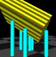
Perhaps a better approach is to design a fixture into which the part can be dropped such that it is guaranteed to come to rest in contact with all fixels. Click on the image below to see a simulation based on rigid body dynamics.

|
For a brief description of rigid body dynamics, some more interesting animations, and links to related papers, click here.