Entity-Relationship (ER) Models
Overview
- Entity-relationship (ER) modeling is a method for designing databases.
- It helps give the high-level view of the whole database, while normalization is more geared towards optimizing individual relations.
- ER models are also meant to help you modularize your database design so that most normalization decisions are easier, often at the entity level.
- ER models are object-oriented, not relational (despite the obvious name). They can be mapped to different data models, but we will see relational data models.
- There is no single accepted notation for ER models, so it is important that you understand the convention used for a specific one you encounter before making assumptions.
- ER is not the only way to model a database, but it is one of the most popular.
ER Data Models
- ER Data models design a whole database using entities and
relationships.
- Remember: this is not a relational data model. So, a relationship is not necessarily a relation.
- We will use pictures to demonstrate the full database model. Once we understand the model, we will see different ways to convert it to the relational data model.
Entity Classes
- Entities are the main building blocks of your database, representing a class of objects we would like to store information about.
- An entity has multiple attributes.
- Attributes of an entity must be simple values.
- This is a departure than the convention used in other places, so be careful. We will only look at simply values: no sets or multi-valued attributes.
- An entity must have a key. The key may be one or more attributes.
- The key defines what the entity means. Entities without keys have no real meaning.
Notation
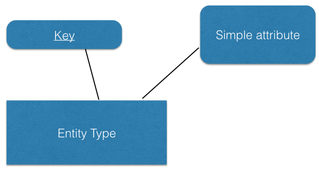
- Use boxes for entities with names in them
- Use ellipses for attributes with names in them
- Underline all attributes of a key
- If there are multiple keys, mark them elsewhere
- If you want to list relevant functional dependencies, mark them elsewhere
- A good practice is to use plural names for entity names: People,
Students, Faculty, Companies
- Each entity in the entity class will be an instance of it: person, student, faculty, company
Key selection for entities
- Aim for real attributes as much as possible when choosing keys instead of inventing IDs.
- Think of an entity as a relation.
- The key of an entity must imply all its other attributes: i.e. the entity must be in BCNF, and if that is not possible in 3NF.
- Get in the habit of thinking of all functional dependencies that apply to an entity and checking that the entity is in BCNF.
Attributes for entities
Make sure the entity does not have an attribute that relates to another entity.
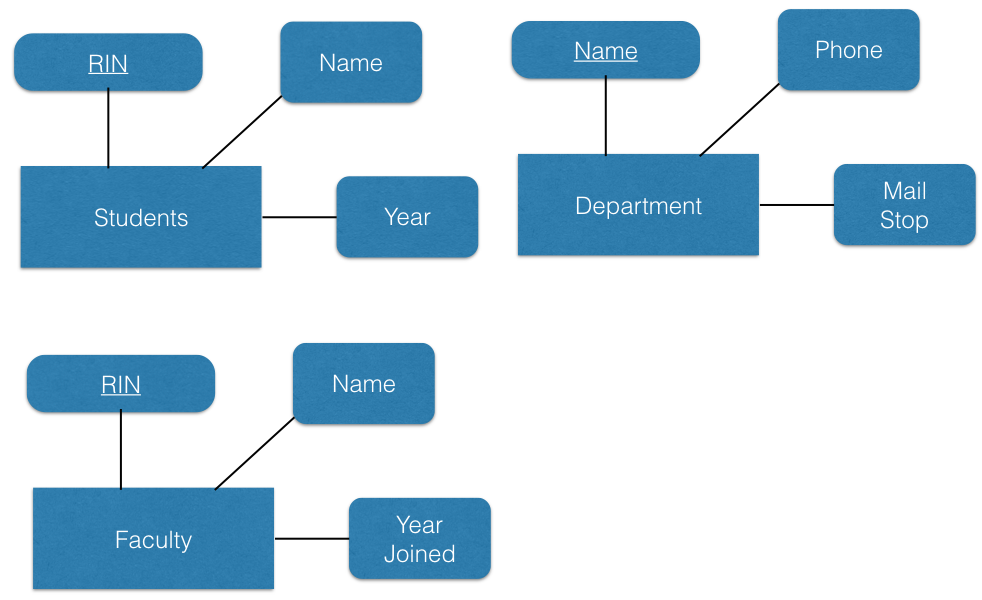
Example: entities Students and Faculty
Faculty: id, name { id -> name }
Students: id,name { id -> name }
Note: advisor is not a good attribute for students as it refers to a faculty. List only attributes of students and students only.
Relationships
- Entities are linked to each other through relationships.
- Think of each relationship as a sentence:
- Entity is-linked-through-relationship-to entity
- Faculty work-in Departments
- Students take Classes
- The relationship is the verb in the sentence, connecting
other entities
- For each combining entity, there is a participation constraint
- Use an arrow to represent a one participation, a rounded arrow means participation is required
- No arrow means many participation
- Remember: most relationships will be binary, it will be rare to have 3-way (ternary) or higher level relationships.
- Note that relationships do not have a key.
- In some other conventions, this is allowed. But, the more restricted model makes it easier to develop simpler and more modular models.
One-to-many relationships
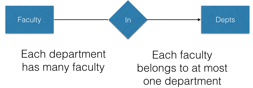
- Use an arrow from entity A to B to mean that for each entity A,
there needs to be exactly one matching entity B.
- Each faculty is in a specific department.
- If there is no arrow from B to A that means that for each entity B,
there can be many entities of type A.
- For a given department, there can be many faculty.
Many-to-many relationships
- Many to many relations are by far the most common. A given student can be in many classes and a class can have many students.

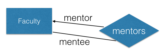
Recursive relationships
- Relationships may connect an entity to itself.
- Roles marked on combining linkes are crucial in determining the cardinality of the relationship for a specific role.
- Each faculty has a single mentor, but a faculty may serve as mentor to many (and has many mentee faculty.)
Relationship attributes
- Relationships may have attributes.
- The attributes should not be about the entities connected, but their relationship to each other.

- In this example, the grade is of a student for a specific class she/he took.
Referential Integrity
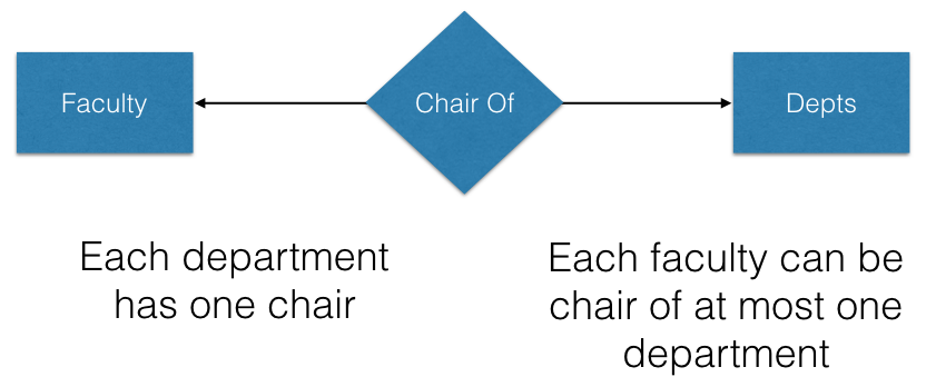
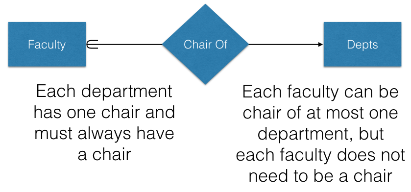
- The regular arrow is used to represent that there is at
most one entity of a given type.
- A faculty can be the chair of at most one department.
- Faculty can be chair of zero departments, and this is by far more common.
- Some books represent this as 0..1 (0 or 1) participation.
- The rounded arrow is used to represent that for an entity A, there
must exist one and only one entity B.
- Each department must have a chair at all times.
- We cannot store departments without chairs.
- Some books represent this as 1 participation (zero is not allowed).
- These strong referential integrity constraints will help avoid incorrect data from being stored, but they will also limit what values can be entered.
- Use the constraints that you know are true and useful, or otherwise your user base will not be happy with you.
- You can even put more complex participating constraints by explicitly listing the number on the relationship link.

- Employees must work in at least 1 and at most 2 teams, and each team must have between 2 to 4 members.
- There are multiple ways to map these to relational data model, but it helps to spell out all relevant constraints at modeling time and then decide which ones enforce in the database depending on the resulting data model and application software.
Ternary relationships
- Not all relationships combine two entities. Ternary relationships are between three separate entities.
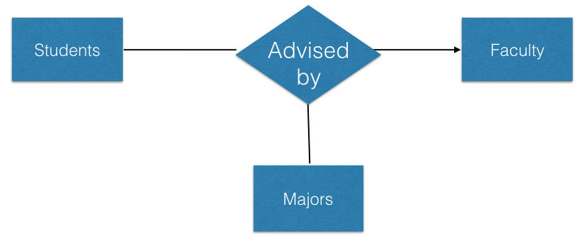
- When deciding the participation constraints, we consider pairs of
attibutes:
- For a specific major and student, there is at most one faculty who is an advisor.
- For a specific advisor and major, there could be many students.
- For specific student and faculty, there could be multiple majors that the faculty is the advisor of (for example cog sci and games major).
Do you really need a ternary relationship?
Many ternary relationships are actually combination of binary relationships! Make sure you really need a ternary relationship.
Example:
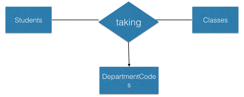
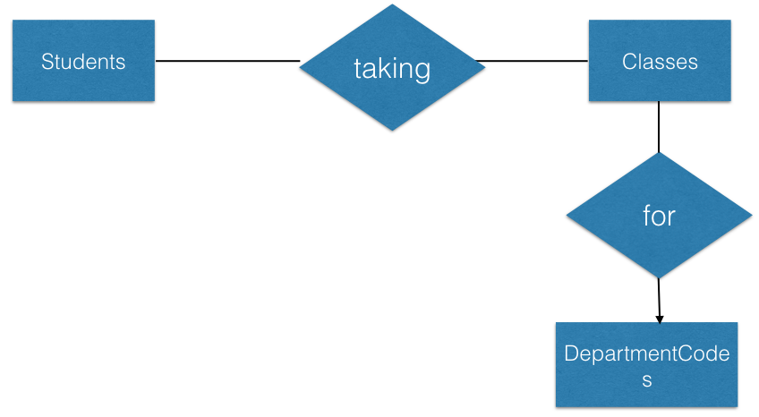
Classes can be cross listed. But, assume a given CRN for a class is for a specific department code.
The department code of a class is not dependent on the student, but the actually class. Hence, no need to use a ternary relationship!
In fact, you realize that it is the case that:
classid -> departmentcode
Hence, the departmentcode has nothing to do with the student.
In this case, we should really use the following model:
Lossless decomposition or not
- Consider our earlier model.
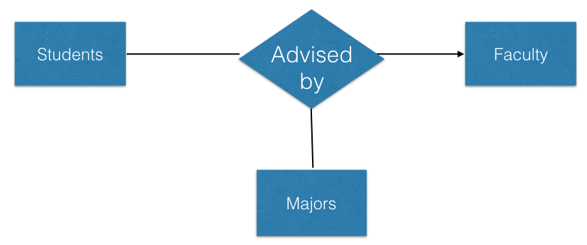
Suppose it is the case that a faculty can advise multiple majors, then the major is not implied from a given faculty.
The arrow implies the following functional dependency between the entities in a relation involving the keys of the three entities:
AdvisedBy(student, major, faculty)  student, major -> faculty
Key: student, major
Suppose, we stored the same information using the following model:
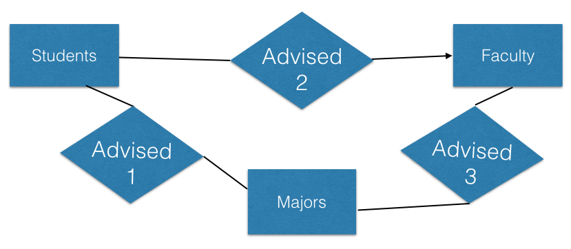
This is not the same data model as before. Either one of the following is true:
If we keep the arrow in advised 2, students can have only one advisor overall.
If we remove the arrow in advised 2, students can have many advisors for the same major also!
This is in fact a lossy decomposition. We can see it using the Chase algorithm with respect to:
AdvisedBy(student, major, faculty)  student, major -> faculty
Decomposed to:
A1(student, major)
A2(student, faculty)
A3(major, faculty)
student major faculty s m f1 s m2 f s3 m f As there is no way to apply the above functional dependency, this is a lossy decomposition.
Weak Entities
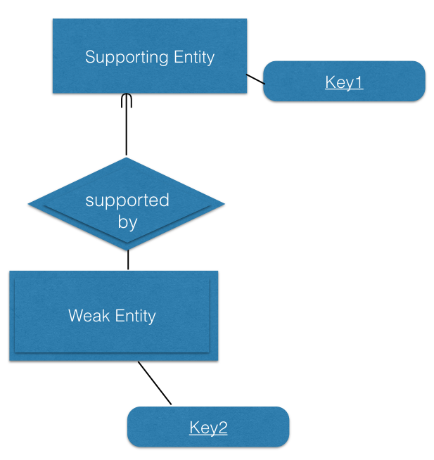
- The key for a weak entity is not guaranteed to be unique in the database
- Think of the weak entity as a special subclass of some other entities
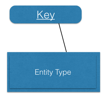
- A weak entity is always linked to one or more (strong) entities.
It is determined by them.
- The combination of the weak entity key with the strong entity it depends on is unique.
- For example: key2 is not unique but key1 and key2 together may be unique.
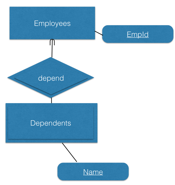
- Names of dependents are not guaranteed to be unique Names of dependents of an employee are guaranteed to be unique
Ternary relationships and weak entities
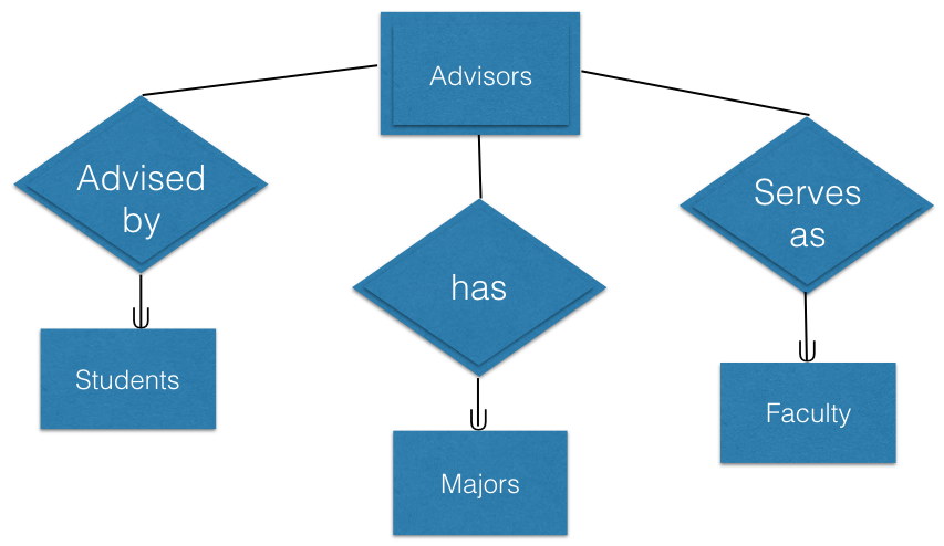
- Ternary relationships can be converted to binary using weak entities
- For each student major and faculty, there is a unique advising entity.
Multivalued attributes and weak entities
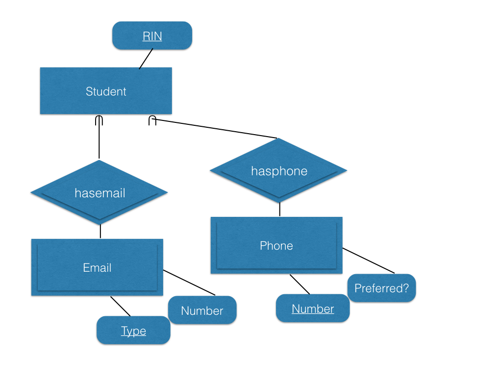
- A common methods is to model multi-valued attributes as weak
entities.
- A student can have many emails.
- A student can have multiple phones.
- Phones and emails are unrelated (as in a multi-valued dependency), hence belong in different weak entities.
Subclasses
- Entities of similar type can be organized in a type hierarchy.
- Unlike type inheritance in programming languages, inheritance in entities is about the attributes the relation has.
- The key and all other attributes are inherited from the parent.
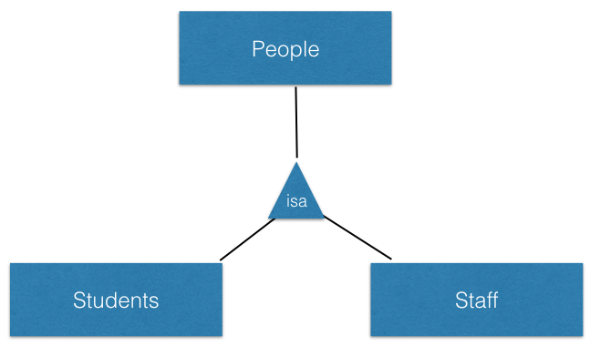
Student & Staff are subclasses of the person entity class.
Student and Staff both inherit the attributes and key of Person.
- Student & Staff are may have attributes special to them.
- A staff entity is a person, attributes related to a person are stored under person.Attributes related to a staff are stored under staff.
Ask the following questions?
Are the subentities disjoint?
Can a person be student and staff at the same time?
Are the subentities covering?
Do the set of all students and staff make up all the people we will store in the database? Are the people who are not student or staff?
Design Rules and Guidelines
- All entities must have a key.The key defines the meaning of the entity.
- If for a class, the key is the code of the class (i.e. CSCI 4380), then we are talking about a catalog class.
- If for a class, the key is the CRN, then we are talking about a specific section of a class that is offered at a specific semester and year.
- If no natural key exists, then it is reasonable to make up an arbitrary one.
- All relationships must be marked with referential integrity and cardinality constraints which are crucial in converting them to the relational model.
- The model must satisfy all the requirements of the given problem, no more no less. (Faitfulness)
- The model must not contain unnecessary information:
- no attributes or relationships that can be inferred from other information should be added
- Repeated data must be put in a separate entities if it makes sense
- Relationships must combine only the entities that are involved in the relationships, binary relationships are better than higher order ones.
- Simpler models are better: if ternary relationships are not needed, then don’t use them.
- Attribute or entity?
- An entity that contains only key attributes may be converted to an attribute.
- Attributes that do not depend solely on the key of the entity must be put in a separate entity.
Example of an unnecessary entity
- A user has a single email, we can simply list it as an attribute of
the student entity.
- Unless there are other relationships specifically connecting to the email entity.
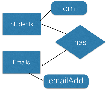
Example of an entity not in BCNF
- Given:
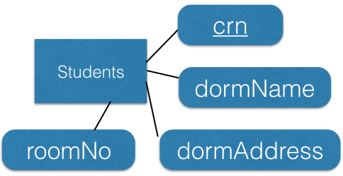
Suppose the following functional dependency holds:
dormName -> dormAddress
This entity is not in BCNF.
We can create a new entity with attributes: dormName and dormAddress.
Here is a better model for the same attributes:
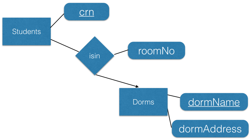
- This one is in BCNF, and we do not have to repeat the same dorm info for different students
Mapping ER to Relational Model
Entities
- Entities are mapped to relations:
- Simple attributes of the entity are mapped to attributes of the mapped relation
- Key of the entity is mapped to the primary key of the mapped relation
Weak Entities
- Weak entities together with their supporting relationships are
mapped to a relation.
- The key of the entity is the combination of the keys of all the supporting entities and the key of the weak entity.
- All attributes of the weak entity are placed in the relation for the weak entity.
Example
- Given:
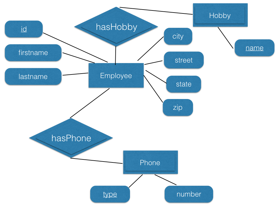
We get:
Employees(Id, firstname, lastname, street, city, state, zip)
Key: Id

EmployeeHobbies(Id, HobbyName)
Key: Id, HobbyName

EmployeePhones(Id,Type,Number)
Key: Id, Type
Converting relationships to ER model
- After converting all entities and weak entities (together with the dependency relationships for the weak entities), we now convert the relationships to the ER model.
One-to-many relationships
- If the relationships is one-to-many, then map the relationship into the may side!

For each A, there is a single B. Then store the B for each A as an attribute:
A(keyforA, attributesforA, keyforB) Key: keyforA

B(keyforB, attributesforB) Key: keyforB
Technically, you can store the relationship as a new relation:
A(keyforA, attributesforA) Key: keyforA
B(keyforB, attributesforB) Key: keyforB

R(keyforA, keyforB) Key: keyforA
But it generally makes sense to combine R and A if we often query them together, hence the first model is better.
Example:

We can add the key for Department in Employee
Employee(..., departmentkey) Key: keyforEmployee
For each employee, there is a single department that they work for. List the key of that department.
One-to-one relationships
- If the relationships is one-to-one, the key for one relation
can be stored in the other relation.
- If one side has a referential integrity, then it is better to use the key of entity that must participate in the relationship as the key.

- Store key for A in B or the key for B in A.
- Example:

As each department must have a chair, better to use key for department.
Department(...., Employeekey) key: keyforDepartment
Many-to-many relationships
- Many to many relationships must be mapped to a new relation. The above methods do not work.
- The key for the relation resulting from the mapping of a many-to-many relationship is the combination of the keys of all the participating entities.

We will get:
R(keyforA, keyforB) Key: keyforA, keyforB
Attributes of relationships
- The attributes of the relationships are mapped to the same relation that the relationship is mapped to.

Relational model:
Aff_with(keyforEmployee, keyforDepartment, title)
key: keyforEmployee, keyforDepartment
Subclasses
- There are three basic ways to map a subclass to relational data model.
- The best model will depend on the underlying class hierarchy: Is it covering and/or disjoint?
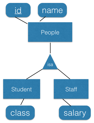
Option 1: store only unique information in each relation
Given the above example, we can map as follows:
Person(personid, name)  Key: personid
Student(personid, class) Key: personid
Staff(personid, salary)  Key: personid
- Store all people in person
- Store additional info in the other relations
Advantages: finding all people is easy
Disadvantages: the information for students and staff is in split into two relations, requiring frequent joins, increasing query time.
Option 2: map each entity to a separate relation
Given the above example, we can map as follows:
Person(personid, name)  Key: personid
Student(personid, name, class)  Key: personid
Staff(personid, name, salary)  Key: personid
Store people who are not student or staff in person
Do not need person relation if there are no people who are not student of staff
Advantages: Information about each relation is not scattered in multiple relations, finding all information about a student or staff is fast
Disadvantage: costly to answer queries about all people, need to union the three relations; may require more work mapping the relationships
Option 3: Combine all the information in a single relation
Given the above example, we can map as follows:
Person(personid, name, student_class, staff_salary, is_person, is_staff)
Key: personid

is_person, is_staff are boolean
If a person can only be a student or staff, a single boolean is enough.
Advantages: fast queries, everything is in a single relation, smaller data model.
Disadvantages: may have a lot of null/empty values for attributes (for example staff_salary is null for all students), all relationships for students and staff are mapped to people making the data model harder to comprehend, document and use.
Example of conversion to relational data model
- Consider the design of a database to manage airline reservations:
- For flights, it contains code and name of the departure and arrival airports, departure and arrival dates and times
- For flights, it also contains a number of different pricing plans with different conditions (Saturday stay, advance booking, etc.)
- For passengers, it contains the name, telephone number and seat type preference
- Reservations include the seat assigned to a passenger
- Passengers can have multiple reservations
- Solution:
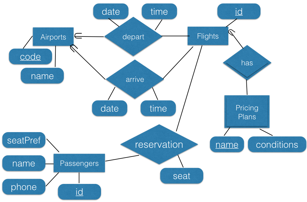
Convert to relational data model (note: pricingplans is a weak entity):
Airports(code, name) Key: code

Flights(id, depAirportCode, depDate, depTime, arrAirportCode, arrDate, ArrTime) Key: id

PricingPlans(flightId, name, conditions) Key: flightid, name

Passengers(id, name, phone, seatPref) Key: id

Reservations(passengerId, flightid, seat) Key: passengerId, flightid
