The field of rigid body dynamic (more generally, multibody dynamics) is all about designing mathematical models and algorithms to predict the motions of bodies and the contact forces that arise between them when. The two most exciting applications of rigid body dynamics are in robotics and computer games, but there are also many other important engineering applications, like assembly and machine design. In robotics, the goal is to build a robot with the capability to plan and autonomously carry out dexterous manipulation tasks - like doing the dishes. More and more, computer games contain physics engines to improve realism - for example, dropping a stone into the gears of a machine could cause jamming, thus stopping the knife blades from swinging across your path, and allowing you to escape the collapsing building.
Applications of rigid body dynamics to robotics and computer games differ in a critical way. In computer games, the physics engine must produce physically plausible body motions in hard-real-time. This requires approximations of the "correct" dynamic equations needed in robotics applications. In robotics, the physics engine is used to answer the question, "Given the input (motor torques, gravity, etc.), tell me how the robot will move and what contact forces will arise in the process. This is the forward problem. For example, if a robot moves its arm in a specified way that causes it to hit a box on a table, the solution to the forward problem provides a prediction of where the box will come to rest, whether it will slide or tumble, and the magnitudes and directions of the forces that arise.
Once it becomes possible to accurately predict the consequences of robot actions, it also becomes possible to plan the activities of a robot to achieve a desired goal. Given the current state of the robot and its environment, and a task specified as a goal state of the robot and its environment (the dishes are put away and the robot is in the closet charging itself), planning is equivalent to finding the set of robot actions that transform the robot and environment to a goal state. This inverse problem is extremely challenging and often counter-intuitive (two reasons I like studying rigid body dynamics).
Rigid Body Dynamics with Dry Friction:
Basic Mathematical Character
In the early 1980's Lodtstedt published the first paper I know of in which
the equations of motion of a system of rigid bodies in unilateral contact was
formulated as a complementarity problem. After writing the Newton-Euler
equations (a system of ordinary differential equations (ODEs)) for the bodies,
complementarity conditions were introduced to prevent interpenetration (these
constraints were written at the acceleration level, as opposed to the velocity
or position levels). The Newton-Euler equations were solved for the body
accelerations, which were then eliminated from the complementarity conditions,
yielding a complementarity problem whose unknowns are contact forces.
A complementarity condition is a system of inequalities and equations of the
following form:
Simulation of dynamic rigid body systems using the complementarity formulation requires the solution of a differential complementarity problem (DCP), which can be seen as analogous to an ordinary differential equation (ODE). Time-stepping methods for DCPs require the solution of one or more complementarity problems for each time step, just as the numerical solution of ODEs require several evaluations of the derivative function (a.k.a., the right-hand side). However, it was noted by Lotstedt, that the acceleration-based complementarity formulation does not always admit a finite-force solution (The same kind of problem was found by Painleve in 1895, long before complementarity theory was born). This problem was solved independently in the mid 1990s by Stewart and Trinkle, and by Anitescu and Potra, by reformulating the complementarity problem in terms of velocities and impulses. The main difference between these two methods in their original form is in the formulations of the non-penetration constraints. In the Stewart-Trinkle (ST) time-stepper, the constraints are written in terms of positions, while in the Anitescu-Potra (AP) time-stepper, they are written in term of velocities. This gave the ST time-stepper built-in constraint stabilization, which the AP method had to handle outside the time-stepper.
There are many software packages for multibody dynamics simulation. For a list short list with short descriptions of the basic underlying simulation approach go to my sim_packages page.
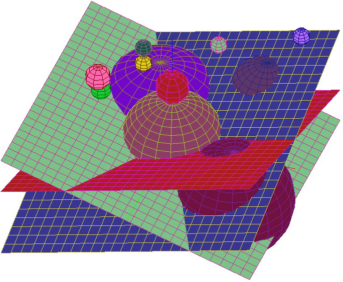
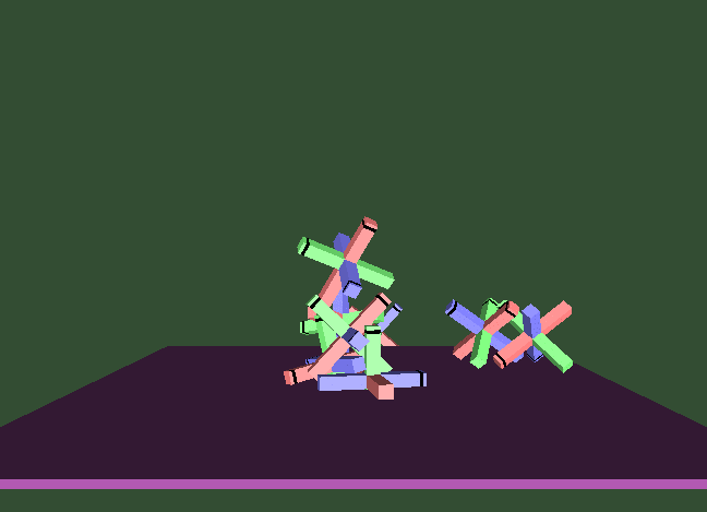
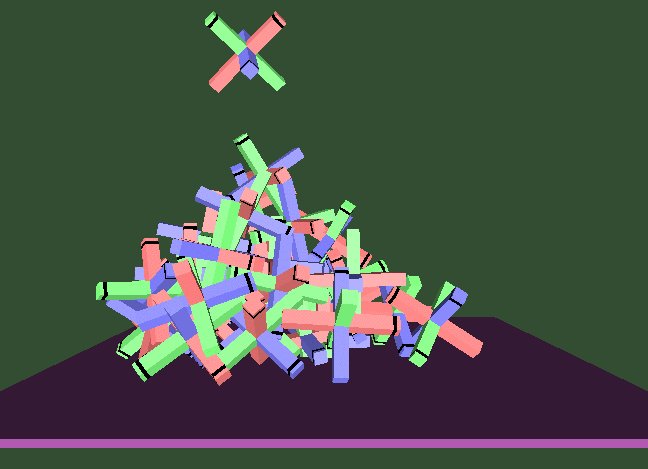
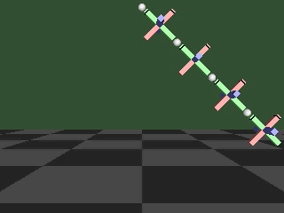
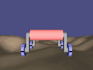
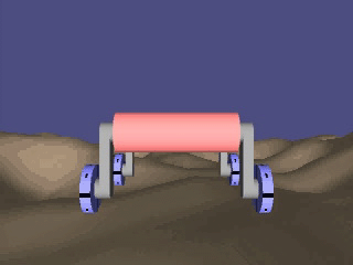
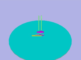
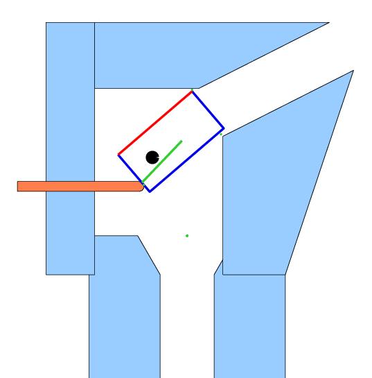
The text Pfeiffer and Glocker, Multibody Dynamics with Unilateral Contacts, Wiley, 1996) contains a complementarity formulation of general rigid body dynamic systems and a section of impressive application results obtained with a straight-forward time-stepping method. You can also visit Pfeiffer's web page here. Brogliato, Non-smooth Mechanics: Models, Dynamics, and Control, 2nded., Springer, 1999, is also worth checking out.
The other popular way are constraint-based methods. This methods are essentially the same as complementarity methods in the following sense. They use the Newton-Euler equations and the same non-penetration constraints as in the complementarity approach. However, rather than formulate a DCP, then formulate a DAE (differential equation with algebraic constraints (see Haug 1982)). The algebraic constraints are obtained by making assumptions about which contacts will be maintained, which will begin to slide, which will separate, etc. In other words, the choices about which complementarity constraints will be active over the next time step(s) is assumed by logic tests in the solver software (e.g., contact A will be maintained, because the normal component of its contact force is large). The main problem with this method is that it does not leverage complementarity theory or complementarity problem solvers.