Advanced Computer Graphics
Contact Information
Office Hours
Syllabus
Prerequisites
Textbook
Grading
Assigned Readings
Calendar
Lecture notes
Lab materials
Homework
Test reviews
Homework
Collaboration Policy
Compilers
gcc/g++ notes
GL/glut notes
Homework Late Policy
Electronic Submission
Final Project
Spring '09 Projects
Spring '08 Projects
Spring '07 Projects
Assignment 1: Simplification and Subdivision Surfaces
The goal of this assignment is to try your hand at various mesh processing tasks. A half-edge mesh adjacency data structure is provided, along with a very simple .obj mesh parser. As you modify the triangle mesh, it is critical that the manifold properties of the input surface are maintained, and that the adjacency data structure remains consistent. Throughout this assignment you are asked to consider the efficiency of various mesh operations: is it quadratic, linear, logarithmic, constant, etc? Since this assignment is rather long, it's ok if you don't always implement the most efficient strategy (which may require additional data structures), but please discuss the tradeoffs in your README.txt file.
Warning: This assignment has two large components (simplification and subdivision). Start early, and just get the basics working first. Spend a reasonable amount of time coding and write about what you've learned in your README.txt file.
Tasks
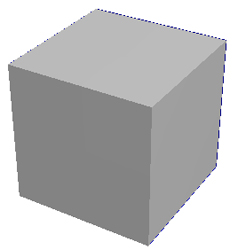
- Download the provided source code and compile it as
before. You should be able to load simple .obj files and turn
wireframe visualization on & off by pressing "w". Try these command
lines:
./mesher -input cube.obj -size 300
./mesher -input cube.obj -size 300 -wireframe
./mesher -input open_box.obj -size 300
./mesher -input open_box.obj -size 300 -wireframe
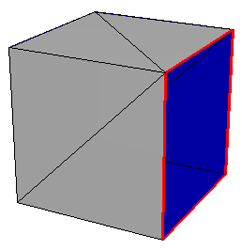
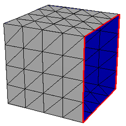
Notice that the adjacency data structure detects boundaries in the mesh and draws them with thicker red lines in the wireframe visualization:
- Now you're ready to start coding. First make use of the
adjacency data structure provided to implement gouraud
shading. In gouraud shading, average normals are computed for
each vertex, these normals are used for lighting, and the shaded
values automatically interpolated in GL. You can change the color
and/or normal between each specified vertex. This shading option
should be enabled by specifying -gouraud on the command line, or
pressing "g".
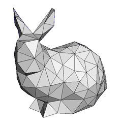
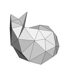
./mesher -input bunny_1k.obj -size 500
./mesher -input bunny_1k.obj -size 500 -gouraud
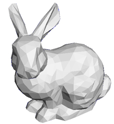
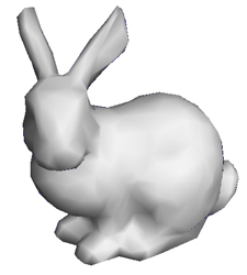
Note that the average normals for each vertex can be efficiently computed without any adjacency information at all, but that wouldn't give you practice with the data structure! For extra credit, don't average the normals across "sharp crease" edges (whose faces differ in normal by more than a user-defined threshhold angle).
Describe in your README.txt file any helper functions you created to implement this shading. Comment on the efficiency of your implementation.
- Next, let's experiment with edge collapses, the key mesh
manipulation operation from the Progressive Mesh framework. When you
press the "d" key (for decimate, a.k.a. simplification) the number of
triangles in your mesh should be reduced by approximately 10 percent.
First implement the topology of an edge collapse. Identify a target edge to collapse. For now, use the function Bag::ChooseRandom() to pick a random edge in the mesh. Using the adjacency data structure, identify which two triangles will be removed permanently from the model, and which other triangles will change. Choose a simple location for the remaining vertex (e.g., it's old position, or a position averaged with the deleted vertex). Note: in the provided adjacency data structure you will delete and then re-create triangles rather than modify them. Initially you may want to just collapse one edge each time the "d" key is pressed. In your README.txt file, describe any helper functions you create.
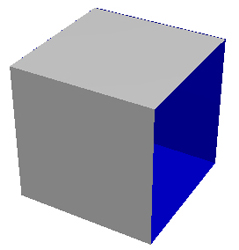
./mesher -input bunny_1k.obj -size 500 -wireframe
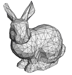
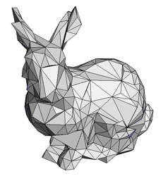
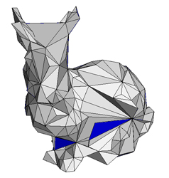
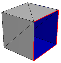
Even though a single random collapse works great, you will probably quickly run into problems: 1) the mesh looks bad with small triangles and big triangles that don't represent the high-resolution model very well, 2) it creates self intersections of the surface (it turns itself inside out and you can see the blue side), and 3) (worst-of-all) it sometimes crashes with an error like:
assertion "opposite == NULL" failed: file "edge.h", line XXX
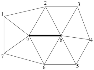
Think about what that error might indicate is wrong with your implementation. (If you get a different error, of course, try to explain that one.) Certain edges should not be collapsed because it would cause the surface to become non-manifold. For example, the "ring" of vertices surrounding the target edge should be unique. In the diagram below, if vertices 1 and 4 refer to the same vertex, then after the collapse of the solid black edge, four triangles will meet at the same edge. Write code to check for these conditions. NOTE: This code can be very complicated. It's ok if you only just catch some of these conditions and your program still crashes occasionally. Don't spend too long trying to make it perfect. Discuss this in your README.txt file.
Now implement something to make a smarter choice for which edge to collapse (this might also minimize the occurance of lingering bugs from the previous part). Collapsing the shortest edge first (or actually make that the shortest legal edge) will usually do a very good job at preserving overall surface shape. Done naively, repeatedly selecting the shortest edge for collapse can be an expensive operation. That's fine for now, you can implement something very inefficient. Discuss these performance issues in your README.txt file and what common data structures would help.
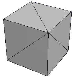
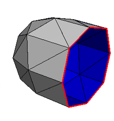
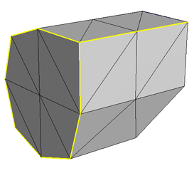
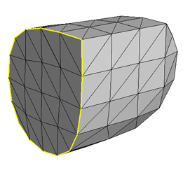
- Finally, implement the Loop Subdivision Surface scheme. When
the "s" key is pressed, your implementation should perform one
iteration of subdivision. First you want to get the topology correct.
Add a vertex at the center of each edge, then replace each triangle
with 4 smaller triangles. Make sure you share the new vertices across
the edges and don't create multiple copies of the vertex. Consider
how to do this efficiently and discuss various options in your
README.txt file. The provided VertexParent class
should be very helpful for this task. You can verify correct vertex
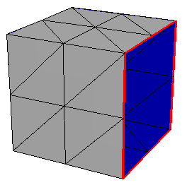
sharing by visualizing the wireframe and looking for the red boundary
edges. If you have extra red lines on your mesh (not at the
boundaries) you have not properly shared the vertices.
./mesher -input open_box.obj -size 300 -wirefame
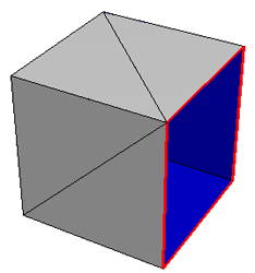
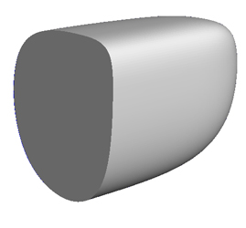
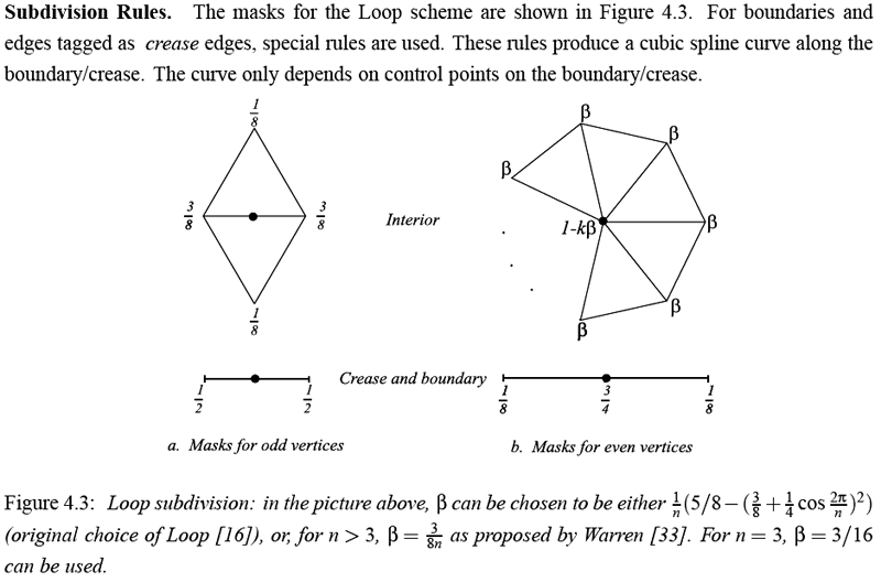
Once you have the correct topology and vertex sharing, you can adjust vertex positions according to the Loop Subdivision rules. To handle general shapes you must implement the rules for regular vertices (valence = 6, i.e., 6 edges meeting at a vertex), extraordinary vertices (valence != 6), and boundary conditions. Here are the Loop Subdivision Rules from the SIGGRAPH 2000 course notes - Subdivision for Modeling and Animation (page 70).

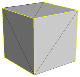
Finish off your subdivision surface code by implementing the simple binary (infinitely sharp or infinitely smooth) crease method described in: "Piecewise Smooth Surface Reconstruction." H. Hoppe, T. DeRose, T. Duchamp, M. Halstead, H. Jin, J. McDonald, J. Schweitzer, W. Stuetzle. ACM SIGGRAPH 1994.
./mesher -input creased_cube.obj -size 300 -wirefame
Ideas for Extra Credit
Include a short paragraph in your README.txt file describing your extensions and sample command lines to demo them.- Implement gouraud shading with a proper average weighted by
angle for the triangles meeting at each vertex (if you haven't done
this already) and a crease angle threshhold. Find or create a mesh
which illustrates these differences.
- Implement a "better" edge weight selection method. First define
your goal for simplification and construct an edge weight function
that matches that goal. E.g., if your goal is to create equilateral
triangles than the shortest edge collapse is a very good choice.
Discuss in your README.txt.
- Implement a better positioning method for the remaining vertex in
an edge collapse. Discuss in your README.txt.
- Implement the geomorph option to smoothly transition
between two different resolutions within a progressive mesh.
- Improve the efficiency of your implementation by using the right
data structures for various operations (hash tables, priority queues,
etc.)
- Implement the integer crease weight control described by "Subdivision
Surfaces in Character Animation", DeRose, Kass & Truong, SIGGRAPH
1998 to perform n iterations of crease subdivision
rules followed by infinite iterations of smooth subdivision.
- Implement the floating point weight control by interpolating
between the nearest integer iterations.
- Implement the butterfly interpolating subdivision surface scheme.
Provided Files (hw1_files.zip)
- Basic Code (vectors.h, matrix.h, matrix.cpp, argparser.h, camera.h, camera.cpp,
glCanvas.h, glCanvas.cpp, main.cpp, Makefile)
Similar to Assignment 1.
- Mesh Library (boundingbox.h,
boundingbox.cpp, vertex.h, triangle.h, edge.h, edge.cpp, mesh.h,
mesh.cpp, vertex_parent.h)
An implementation of the half-edge data structure. The load function will parse simple .obj files.
- templated Bag class (bag.h, utils.h)
This class allows efficient (constant time expected) retrieval and removal of elements, implemented with a hash table. The "extract" function is used to hash elements. It is used by the Mesh code to efficiently find pairings between opposite edges at load time.
- .obj files (cube.obj, creased_cube.obj, open_box.obj, l.obj,
torus.obj, bunny_200.obj, bunny_1k.obj, bunny_40k.obj,
complex.obj)
-
Additional models, from
"Piecewise Smooth Surface Reconstruction", Hoppe et al, 1994:
meshes.zip
Please read the Homework information page again before submitting.